
Analysis and design of DAIKIN air conditioning systems

Open BIM DAIKIN is a free software tool that has been developed to analyse and design VRV (Variable refrigerant volume) and aerothermal air conditioning systems.
The program is integrated in the Open BIM workflow, which allows users to import models from projects that are located on the BIMserver.center platform, and participate in the multi-disciplinary and multi-user collaborative work that Open BIM technology provides.
Starting off
The software has been conceived to perform a realistic design of VRV and aerothermal installations in a BIM project.
To begin to use the program, create a new file and then connect it to an existing BIM project, located on the BIMserver.center platform, which contains a model with the geometry of the building (that has been generated by CAD/BIM programs such as IFC Builder, Revit®, Allplan® or Archicad®).
If the thermal loads have been obtained using CYPETHERM LOADS, the program will design the air conditioning system using those loads.
Design of the air conditioning system
First of all, users must choose which type of system is going to provide the air conditioning in the building:
- VRV system
Up to 64 indoor units are connected to an outdoor unit, using a pipe.
- Aerothermal system
Each indoor unit is connected to an outdoor aerothermal unit.
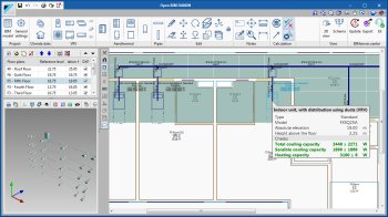
The indoor units of the chosen type of system (cassette, floor, ceiling, wall or ducts) are located in the spaces of the building. In the properties panel, open padlocks can be seen next to the boxes. After the analysis, the program will update the values automatically, of the fields with open padlocks, bearing in mind the information of the spaces and outdoor conditions.
The height at which the pipes are generated is defined in the floor properties panel of the building, which is located on the left of the drawing space.
The vertical pipe spans that are required to meet the elevation differences are generated automatically when elements are connected on the same floor. To create a vertical pipe that joins several floors, the floors to be connected must be made visible in the “Visible floor plans” option (“Edit” section of the toolbar), and, using the “Vertical pipe” command (“Pipes” section of the toolbar), click on the point where the horizontal pipe spans coincide.
Users must indicate the outdoor conditions of the project. If they are unknown, the ASHRAE weather database can be consulted ("Weather data" section of the toolbar > "Location data" button).
Sizing and checks
Once the elements have been sized, the program performs the following actions:
- Checks that the system is connected correctly and there are no design errors
- Checks that pipe lengths and elevation differences between the equipment lie within the allowable range
- Selects the equipment model that is capable of providing the thermal loads of the spaces
- Calculates the corrected power of the equipment depending on the design conditions
- Selects the diameters of the pipes and branches
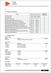
- Measures all the elements of the project and provides a summary in a quantities report
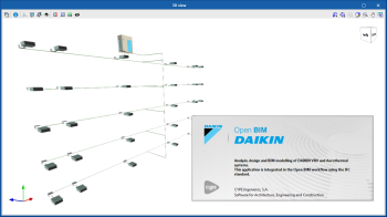
- Automatically generates the diagram of the installation
Results
“Open BIM DAIKIN” provides the following results documents:
- Design report (includes the diagram of the installation)
- Quantities in bc3 format
- Report with materials schedule
Open BIM workflow
The program currently performs the following exchange of information with the linked BIM project:
- Imports
- All the 3D models
Open BIM DAIKIN shows the 3D view of all the models that are imported during the connection with or update of the BIM project.
- The architectural model
As well as showing the 3D view, Open BIM DAIKIN obtains the floor distribution and the indoor and outdoor geometry that is shown on the 2D floors of each floor.
- The thermal loads
The cooling and heating loads that are calculated with CYPETHERM LOADS.
- The suspended ceilings
The program imports the suspended ceilings that have been generated with Open BIM Suspended Ceilings. This way, when users place a cassette, the program detects the height of the suspended ceiling and its centre point, so it is centred on the panel.
- All the 3D models
- Exports
- The 3D model of the designed installation (GLTF)
The program provides the BIM model with the 3D representation of the designed air conditioning installation. This way it is visible in all the 3D views of all the applications that are connected to the BIM model of the project.
- The equipment for the energy simulation
The models of the indoor and outdoor units, and the maximum pipe lengths are exported and read by energy simulation programs EPLUS and HE PLUS.
-
The diagram of the installation (DXF)
-
Design report (PDF)
-
Materials schedule (PDF)
- The 3D model of the designed installation (GLTF)
This flow of data implies, as well as a saving a significant amount of time not having to introduce the data in each project phase, that the number of errors is minimised when architectural modifications arise.
More information
Download, resources and available languages, license requirements...
Tel. USA (+1) 202 569 8902 // UK (+44) 20 3608 1448 // Spain (+34) 965 922 550 - Fax (+34) 965 124 950